Actuators AVD

0%
Presentation
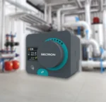
AVD actuators are intended for position control of rotary mixing and ball valves. They are distinguished by robust construction and quiet operation. Innovative accessories provide a quick installation and removal, mostly without any tools.
- For controlling mixing valves in heating or cooling systems.
- Switchover between heating and cooling.
- Switchover between heating and domestic hot water heating.
- Switchover between various heat sources.
- Various other central heating devices.
Features
- Fits rotary mixing valves or ball valves complying with ISO 5211.
- The actuators feature four different installation positions on the valve.
- Resistant to mixing valve blockages.
- The installation and removal can be mostly completed without any tools.
- Operation indication with LED lights.
- An easy replacement of the power cord if damaged.
- A permanent clutch features a switchover between the automatic and manual operation modes. During a switchover, the actuator is switched off electrically.
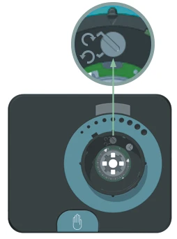
- Option of adjusting the turning direction and operation functions, without interference with the actuator interior.
Documentation
Download
Outlined functions
Universal 2- or 3-point operation
Clutch for manual operation
Quick installation
Plug-in connector
AUX switch
Technical data
| Tehnični podatki | AVD |
|---|---|
| Connection voltage | 230 V~ or 24 V~ |
| Own consumption | 2.5–5 W |
| Degree of protection | IP 42 |
| Safety class | II for the voltage of 230 V~, III for the voltage of 24 V~/V= |
| Applied standards | EN 60730-1, EN 60730-2-14 |
| Housing material | PC - dark grey |
| Standard cable length | 2 m |
| Operating temperature | 0÷50 °C |
| Storage temperature | -20÷75 °C |
| Product weight | 390÷860 g |
| Number of pieces in a package unit | 24 pieces |
| Dimensions |  |
| Electrical connection |  |
Performance comparison
| AVD | AVDS | AVDR | AVDRS | AVDU | AVDUS | AVDY | AVDM | |
|---|---|---|---|---|---|---|---|---|
| Application | ||||||||
| For controlling mixing valves in heating or cooling systems |  |  | — | — |  |  |  |  |
| Switchover between heating and cooling |  |  |  |  |  |  |  |  |
| Switchover between heating and domestic hot water heating |  |  |  |  |  |  |  |  |
| Switchover between various heat sources |  |  |  |  |  |  |  |  |
| Various other central heating devices |  |  |  |  |  |  |  |  |
| Torque | ||||||||
| 5 Nm |  |  |  |  |  |  | — |  |
| 10 Nm |  |  |  |  |  |  |  |  |
| 15 Nm |  |  |  |  |  |  |  |  |
| Operation mode | ||||||||
| Two-point | — | — |  |  |  |  | — | — |
| Three-point |  |  | — | — |  |  | — | — |
| Proporcionalno 0(2)÷10 V ali 0(4)÷20 mA | — | — | — | — | — | — |  | — |
| PWM control signal | — | — | — | — | — | — |  | — |
| ModBus | — | — | — | — | — | — | — |  |
| Pump ON switch | ||||||||
| Adjustable auxiliary switch for activating the circulation pump in any actuator position | — |  | — |  | — |  | — | — |
| Possible running speeds | ||||||||
| 15 s/90 ° | 5 Nm | 5 Nm | 5 Nm | 5 Nm | 5 Nm | 5 Nm | — | — |
| 30 s/90 ° | 5 Nm | 5 Nm | 5 Nm | 5 Nm | 5 Nm | 5 Nm | — | — |
| 60 s/90 ° |  |  |  |  |  |  |  |  |
| 120 s/90 ° |  |  |  |  |  |  |  |  |
| 240 s/90 ° |  |  |  |  |  |  | — | — |
| 480 s/90 ° |  |  |  |  |  |  | — | — |
| Power supply | ||||||||
| 230 V~, 50 Hz |  |  |  |  |  |  | — | — |
| 24 V~, 50 Hz |  |  |  |  |  |  |  |  |
| 24 V= | — | — | — | — | — | — |  |  |
| Operation display | ||||||||
| Display of valve turning direction with LED lights |  |  |  |  |  |  |  |  |
| Valve position indication on the scale |  |  |  |  |  |  |  |  |
| Indication of the auxiliary (AUX) switch activation | — |  | — |  | — | — | — | — |
| Resistant to mixing valve blockages |  |  |  |  |  |  |  |  |
| Installation | ||||||||
| Fits rotary mixing valves or ball valves complying with ISO 5211 |  |  |  |  |  |  |  |  |
| The installation and removal can be mostly completed without any tools |  |  |  |  |  |  |  |  |
| The actuators feature four different installation positions |  |  |  |  |  |  |  |  |
| Connection cable fitted with a connector |  |  |  |  |  |  |  |  |
| Turning direction adjustment and operation functions, without interference with the actuator interior |  |  |  |  |  |  |  |  |
| A permanent clutch features a switchover between the automatic and manual operation modes. During a switchover, the actuator is switched off electrically. |  |  |  |  |  |  |  |  |


